-40%
USB card WEB-TC
$ 348.47
- Description
- Size Guide
Description
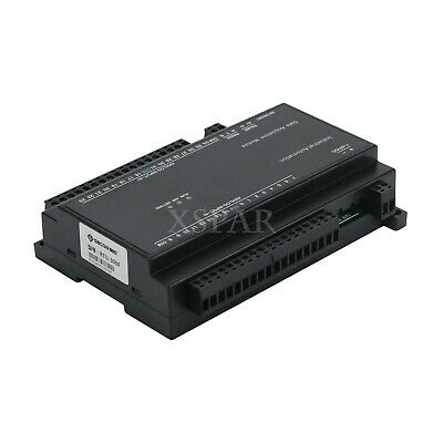
USB card with 8 thermocouple input channels J, K, R, S, T, N, E and B for temperature acquisition via WEB server. 24-bit resolution. Built-in ambient temperature sensor.The WEB-TC is a thermocouple measueremnt device with a built-in web server. Ypu can connect de device to an ethernet port or hub, start up you browser, and view a current data. The WEB-TC is fully supported by the Universal Library and TracerDAQ. These software programs are included on the CD.
Web Interface.
The WEB-TC embedded web interface provides access to current data and configuration settings using a standard web browser. Browse to the device's home page by entering the URL tht is printed on the device into the browser. View current thermocouple measueremnts and channel data, and configure hardware options from the device´s home page. Only one user can change configuration options on the device at time. The web interface is built into the device´s firmware. and does not need to be intalled on a computer. No external software required other than a web browser TCP/IP connection.
TCP/IP connection
A TCP/IP connection is required to acces the web interface. Connect the device´s 10Base-T Ethernet port to a local or wide are network using the supplied Etherned cable, to a sinlge computer trough a hub using the supplied Ethernet cable, or direcly to a computer using standard CAT-5 crossover cable.
WEB-TC Features
The WEB-TC provides eight thermocouple channels and eight digital I/O channels. An external supply shipped with the devi8ce provides de power. On-board LEDs display the status of communication and xternal power. All hardware configurable options are selectable with the web browser or InstaCal. Network configurable aptions are settable with InstaCal. When using InstCal, if the login settings have been changed from the default, a login name and password are required to change the configuration settings.
Thermocouple input channels.
The WEB-TC provides eight differential thermocouple input channels. A 24-bit analog-to-digital (A/D) coveter is provided for each pair of analog inputs. You can take measuremnts from type J, K, R, S, T, N, E, an B thermocouples. The the thermocouple type is software programmable for each channel. Four cold junction compensatin (CJC) sensors are provided for thermocouple measurements. Each CJC sensor is dedicated to two thermocouple input channels. An open thermocouple detection feature lets you detect a broken thermocouple. An on-board microprocessor automatically linerizes the meausremnt data.
Alarms
The WEB-TC features eight independent temperature alarms. Each alarm controls an associated digital I/O channel as an alarm output. The input to each alarm is one of the temperature input channels. The output of each alarm is software-configurable as active high or low. The user-configurable threshold conditions activate each alarm. When an alarm is activated, the associated DIO channel is driven to the active output state selected.
Digital I/O channels
Eight digital I/O channels are provided to communicate with external devices and to generate alarms. The digital bits are software programmable for input or output. The digital output voltage is switch-selectable for 3.3 V or 5 V logic. A screw terminal is provided for pull-up or pull-down configuration. The digital I/O channels power up in input mode unless the bit is configured for an alarm. When a digital bit is configured as an alarm, that bit is configured as an output and assumes the state defined by the alarm configuration.
Features:
24-bit resolution
8 thermocouple input channels
Supports TC types: J, K, R, S, T, N, E and B
Built-in ambient temperature sensor
Separate temperature inputs
8 digital bits of Input/Output
;
TECHNICAL SPECIFICATIONS
Digital input/output
Digital type
CMOS
Number of I/O
8 (DIO0 through DIO7)
Configuration
Independently configured for input or output.
Switch selectable output voltages: +5 V and +3.3 V
Power on conditions
Power on reset is Input mode except when bits are configured to operate as alarms.
Pull-up/pull-down configuration
All pins are connected to 47 kOhm resistors that share a common point accessible at Pin 22 of the device (PU/D). This pin is floating by default and is userconfigurable via external connection. For pull-up mode, connect this pin to Pin 21 (+5V). For pull-down mode, connect this pin to Pin 48 (GND).
Digital I/O transfer rate (software paced)
Digital input – 50 port reads or single bit reads per second typical.
Digital output – 100 port writes or single bit writes per second typical.
Input high voltage (+5 V mode)
4 V min, 5.5 V absolute max.
Input high voltage (+3.3 V mode)
2.64 V min, 5.5 V absolute max.
Input low voltage (+5 V mode)
1 V max., -0.3 V absolute min.
Input low voltage (+3.3 V mode)
0.66 V max., -0.3 V absolute min.
Output low voltage (IOL = 2.5 mA)
0.6 V max.
Output high voltage (IOH=-2.5 mA)
4.3 V min. (+5 V mode), 2.7 V (+3.3 V mode)
Temperature alarms
Number of alarms
8 (one per digital I/O line)
Alarm functionality
Each alarm controls its associated digital I/O line as an alarm output. The input to each alarm may be any of the analog temperature input channels. When an alarm is enabled, its associated I/O line is set to output and driven to the appropriate state determined by the alarm options and input temperature. The alarm configurations are stored in non-volatile memory and are loaded at power on.
Alarm input modes
Alarm when input temperature > T1
Alarm when input temperature > T1, reset alarm when input temperature goes below T2
Alarm when input temperature < T1
Alarm when input temperature < T1, reset alarm when input temperature goes above T2
Alarm when input temperature is < T1 or > T2
Note: T1 and T2 may be independently set for each alarm.
Alarm output modes
Disabled, digital I/O line may be used for normal operation
Enabled, active high output (digital I/O line goes high when alarm condition is met)
Enabled, active low output (digital I/O line goes low when alarm condition is met)
Alarm update rate
1 second
Memory
EEPROM
512 bytes for sensor configuration
FLASH
2 MB for device configuration and website storage
Microcontroller
Type
One high-performance 8-bit RISC microcontroller (isolated)
One high-performance 16-bit RISC microcontroller (non-isolated)
Power
Supply current Continuous mode
440 mA max.
External power input
+5 VDC ± 5%
(+5 VDC power supply provided)
External power supply (included)
MCC p/n PS-5V2AEPS +5 VDC, 10W, 5% regulation
Voltage supervisor limits
4.75 V > Vext or Vext > 5.25 V PWR LED = Off; (power fault)
4.75 V < Vext < 5.25 V PWR LED = On
User output voltage range
Available at +5V screw terminal 4.65 V min., 5.25 V max.
User output current available
Available at +5V screw terminal 10 mA max
Ethernet compliance
Device type
IEEE 802.3 Ethernet 10Base-T
Device compatibility
IEEE 802.3-2003 10 Mpbs Media Access Control
Ethernet connection
Ethernet type
10Base-T
Connector
RJ-45, 8 position
Cable
CAT-5 shielded, unshielded twisted pair
Length
100 meters max.
MAC address
00:12:71:Cx:xx:xx, where xxxxx is the device’s serial number
Environment
Operating temperature range
0 to 55 ° C
Storage temperature range
-40 to 85 ° C
Humidity
0 to 90% non-condensing
Mechanical
Dimensions
127 mm (L) x 88.9 mm (W) x 35.56 (H)
Screw terminal connector type and pin out
Connector type
Screw terminal
Wire gauge range
16 AWG to 30 AWG

